Technical Supplement No BKTSK001 - Front Outrigger Replacement |
The Rover P4 Drivers Guild make every effort to ensure thet the information and advice published is reliable and make proper reference to safety procedures. We are unable to accept responsibility for injury, damage or loss resulting from omission or error. |
Workshop Manual Reference Section K (all models) |
Compiled: Barry Kensett This revision 18 January 2014 |
Rover P4 Front Outrigger Replacement.
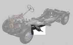
The front outriggers on the Rover chassis are subjected to the blast of water and salt from the front wheels and not surprisingly are a common corrosion point. The forward face and the bottom section usually suffer first and these can be patched. When the outer face which supports the body mounting starts to break up there is little access to do a permanent repair and a more drastic treatment is required. An additional major problem is caused by the collection of water in the bottom of the outrigger which cannot escape but can penetrate the joint with the main chassis member and corrode through the chassis at this point. The best access to carry out replacement is with the body off; I have heard of people who raise the body about a foot which can usually be done in the garage with normal lifting tackle. I have also heard of people waving their welding torch blind in the gap between the outrigger and the floor - the mind boggles!
Faced with the breakout of the body mounting I talked to a few experts and decided to change the outriggers without removing the body and to get access to the top I cut two access holes in the floor 9 inches by 3 inches using a nibbler (had I used a grinder there was a danger of nicking the hydraulic pipes on the offside). I then jacked the car up about two feet and removed the master cylinder and its rod along with the handbrake and its front rod. It is then possible to cut the outriggers off with an angle grinder and clean up the faces to receive replacements. There is a slight complication on the offside with the master cylinder mounting bracket; I cut this by gouging into the outrigger to leave the bracket intact for welding to the new outrigger. I needn't have bothered as the new outrigger sat in a slightly different position and the bracket had to be extended anyway. There is no need to take the bracket off of the chassis member. Once the outriggers were off I found that the chassis was rusted through where water had collected in the bottom flange but this damage had not extended beyond the outrigger flange. I therefore was able to weld an insert into the chassis before fitting the new outriggers.
I elected to use the ready made new outriggers which are on the market and which fitted reasonably well. The flanges were long but were easily cut back. The height was about an eighth of an inch to small to fit over my chassis but I cut the weld for about one inch on the bottom flange which enabled it to be sprung open sufficiently. The cut was then welded up. I had to trim the vertical faces very slightly to get a close fit.
The outer end of the outrigger was located in the sill using new mountings but I used a bolt with a turned down shank to set the outrigger 0.1" high to ensure that it carried its share of body weight. The zinc plate was removed from all welding faces. Whilst I usually prefer gas welding, I used MIG to attach the outrigger to the chassis as the amount of heat needed would have set fire to the underseal on the floor. The welding is very straightforward but needs at least 130 amps to get the right penetration (this is about the limit on a 13 amp plug). Bronze welding would be strong enough and uses less heat but I felt that the slight pitting on the chassis would make it difficult to tin properly, particularly on the overhead weld where balls of molten metal up the sleeve are a hazard at the best of times. I should have painted the inside of the outriggers before welding them on; it would have been a lot easier on the bench!
As mentioned earlier, I extended the master cylinder bracket to meet the outrigger face which sat a little forward of the original. I lapped the extension onto the old bracket and fillet welded it to the outrigger being careful to leave space for the jacking point.
The undersize bolt was removed from the body mounting by removing the bolts through the outrigger the provide clearance to extract it. The sill was then jacked to line up the bolt hole and a packer was made to fill the gap between the mount and the sill. The jacking points, handbrake, master cylinder and rods were then replaced. I finally made up a pair of panels to close up the floor.
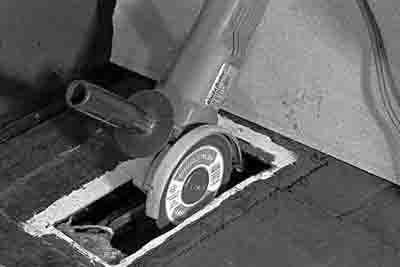
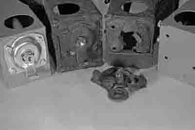
Illustations below show (left) the access hole cut in the floor and the use of a grinder to cut off the old outrigger and (right) the state of the old outiggers showing the body mountings which had torn away from the structure alongside new outriggers and mounts.
©B.Kensett 2023